Cell phone cameras have become an integral part of our daily lives. We use them to capture memorable moments and share them with our loved ones. However, have you ever wondered how the camera works? In this article, we will guide you through the process of creating a DIY cell phone camera wiring diagram.

What is a cell phone camera wiring diagram?
A cell phone camera wiring diagram is a schematic representation of the various components that make up a cell phone camera. It shows how the camera sensor, lens, flash, and other components are connected to the main circuit board. By understanding the wiring diagram, you can troubleshoot and repair any issues with your cell phone camera.
Tools and Materials Required
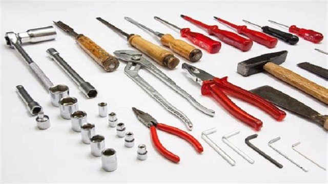
Before you start creating the wiring diagram, you will need a few tools and materials. These include:
- Soldering iron and solder
- Wire strippers
- Multi-meter
- Cell phone camera module
- Thin wires
- Small screwdriver
- Hot glue gun
Step-by-Step Guide
Now that you have gathered all the necessary tools and materials, let’s get started with creating the wiring diagram:
Step 1: Disassemble the cell phone
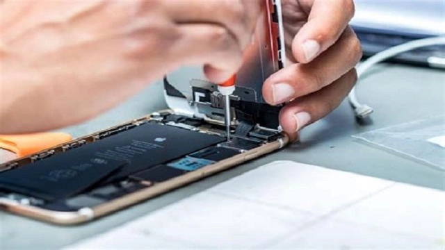
The first step is to disassemble the cell phone and remove the camera module. This can be done by using a small screwdriver to remove the back cover and unscrewing any screws that hold the camera module in place. Be careful not to damage any of the components during this process.
Step 2: Identify the camera module pins
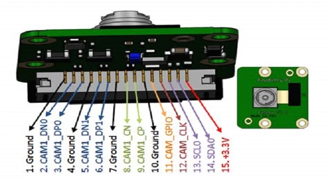
Once you have removed the camera module, you need to identify the pins on the module. These are usually labeled on the back of the module. If they are not labeled, you can use a multi-meter to identify the pins.
Step 3: Connect the wires to the camera module
Next, you need to connect the thin wires to the camera module pins. Use the wire strippers to strip a small section of the wire, and then solder it to the pin. Repeat this process for all the pins on the camera module. Be sure to label each wire according to its corresponding pin.
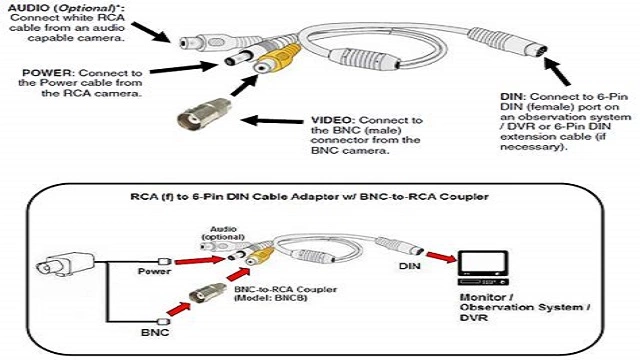
Step 4: Create a circuit diagram

Now that you have connected the wires to the camera module, you need to create a circuit diagram. This will help you understand how the components are connected and how they work together.
Step 5: Connect the camera module to the main circuit board
The next step is to connect the camera module to the main circuit board. This can be done by soldering the wires to the appropriate pins on the circuit board. Be sure to follow the circuit diagram carefully to avoid any mistakes.
Step 6: Test the camera
Once you have connected the camera module to the circuit board, it’s time to test the camera. Reassemble the cell phone and turn it on. Open the camera app and test the camera by taking a few pictures and videos. If everything works well, congratulations!
Conclusion
Creating a DIY cell phone camera wiring diagram is not an easy task, but it can be a fun and rewarding experience. By following the steps outlined in this article, you can gain a better understanding of how your cell phone camera works and troubleshoot any issues that may arise. Remember to work carefully and patiently, and don’t hesitate to seek help from a professional if needed.
Rekomendasi Lain:
- Bluetooth Speaker with Spy Camera: The Ultimate Combination… Bluetooth speakers have become a ubiquitous accessory for anyone who loves music, podcasts, or audiobooks. They can be carried anywhere, have excellent battery life, and offer impressive sound quality. But…
- Can Blink Cameras Be Hacked? Blink cameras are one of the most popular home security cameras on the market. They are easy to install, affordable, and offer excellent features. However, many people are concerned about…
- Best Camera for Self Filming Hunts Self filming hunts has become a popular trend among hunters. It allows them to capture their hunting experiences and share it with others. To capture those moments, one needs a…
- Security Camera with SIM Card Security cameras have become an essential part of our daily lives, especially when it comes to ensuring the safety of our homes and workplaces. The latest addition to the security…
- Security Camera DVR with Hard Drive Security cameras and DVRs (digital video recorders) have become an essential part of modern security systems. They are used to monitor and record activities in homes, offices, and public places.…
- Best Camera for Concert Photography Concert photography is a unique form of photography that requires a special set of skills and equipment. Capturing the energy and excitement of a live performance can be challenging, but…
- Apple CarPlay Stereo with Backup Camera Driving can be a hassle, but with the right technology, it can be more enjoyable and safer. Apple CarPlay Stereo with Backup Camera is one of those technologies that make…
- Best Video Camera for Podcasting Podcasting is a great way to share your ideas and connect with your audience. However, to make your podcast sound professional, you need a good video camera. A good video…
- How to Enable Facetime Photos Facetime is a great way to stay in touch with friends and family, especially during these times when we can't always be physically together. One of the great features of…
- Dog with Nose in Camera Dogs are known for their adorable nature, and they never fail to make us smile. One of the cutest things that they do is put their nose in the camera…
- Wireless Backup Camera for Phone Driving can be a risky affair, especially when you are backing up. Blind spots, obstacles, and other vehicles can make it challenging to maneuver your car, truck, or SUV. This…
- Glasses with Camera Built In Are you tired of fumbling around with your phone to capture the perfect moment? Do you wish you had a hands-free way to document your adventures? Look no further than…
- Do All Canon Lenses Fit All Canon Cameras? When it comes to buying a new camera lens, one of the most common questions that people ask is whether all Canon lenses fit all Canon cameras. The answer to…
- USB Hidden Camera with Audio Are you looking for a way to keep an eye on your home or office without anyone knowing? A USB hidden camera with audio may be the perfect solution for…
- DIY Drone Kit with Camera: Building Your Own Aerial… Are you interested in aerial photography but don't want to spend a fortune on a ready-to-fly drone? Why not build your own drone kit with a camera? Not only is…
- Do Blink Cameras Work with Google Home? If you own a Blink camera and a Google Home, you may be wondering if the two devices are compatible. The good news is that, yes, Blink cameras work with…
- Flash for Sony Mirrorless Camera Sony mirrorless cameras are becoming increasingly popular among photographers due to their compact size and impressive image quality. However, many users are unaware that they can improve their photography even…
- Best Peephole Camera for Apartment Living in an apartment can be challenging when it comes to security. You can never be too sure who is knocking on your door. That's why having a peephole camera…
- Double Din Car Stereo with Backup Camera Are you looking for a new car stereo that can do more than just play music? A double din car stereo with backup camera is the perfect solution. This type…
- Best Video Camera Under $1000 When it comes to creating high-quality video content, having the right equipment can make all the difference. While there are certainly expensive cameras on the market that can produce stunning…
- Best Camera for Jewelry Photography When it comes to jewelry photography, having the right camera is crucial to capture the intricate details and showcase the beauty of the pieces. With so many options available in…
- Best Cameras for Car Photography Car photography is a popular niche in the world of photography. Whether you are a car enthusiast or a professional photographer, capturing the beauty of a car is a challenge…
- Hidden Camera with Built-in DVR: The Ultimate Solution for… If you're looking for a discreet and effective way to monitor your home or business, a hidden camera with built-in DVR might be the perfect solution. These cameras are designed…
- Best Wireless Backup Camera for RV If you own an RV, you understand the importance of having a good backup camera. It makes maneuvering your vehicle much easier while increasing your safety on the road. However,…
- Best Digital Camera Under $300 Are you looking for a digital camera that won't break the bank? With so many options on the market, it can be challenging to find the right one. However, you…
- Canon EOS Rebel T100 DSLR Camera with 18-55mm Lens If you're looking for a reliable and affordable DSLR camera, the Canon EOS Rebel T100 with 18-55mm lens might be the perfect option for you. The camera is designed for…
- Does Ring Camera Record All the Time? If you are considering purchasing a Ring camera, you may be wondering whether it records all the time or only when it detects motion. This is an important question to…
- Spypoint Flex Cellular Trail Camera Reviews Trail cameras have become increasingly popular among hunters and outdoor enthusiasts. The Spypoint Flex Cellular Trail Camera is a popular option that offers a range of features that make it…
- Electroplated iPhone Case with Camera Protector If you're looking for an iPhone case that's both stylish and functional, you might want to consider an electroplated iPhone case with a camera protector. These cases are sleek and…
- Best Camera for Live Streaming Church Live streaming has become an integral part of the church community, especially during the pandemic. Churches around the world have turned to live streaming to reach out to their congregation…